|
|
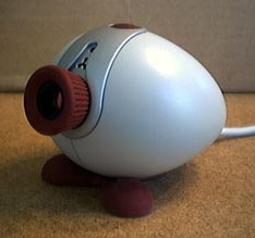 |
Here is the Philips Vesta 675 as it appears to the laymen. This cute little contraption will be reduced to rubble before I'm finished with it.
|
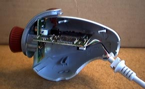 |
It's pretty hard to open the case without breaking the various clips on the inside. I didn't really care because I was going to build my own enclosure anyway. This shot shows how the circuit boards sit sit inside the case. Notice that there are two circuit boards.
|
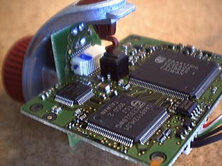 |
Here is a close up showing the interface between the main board and the CCD board. The two boards pull easily apart.
|
 |
This is the top of the main board...
|
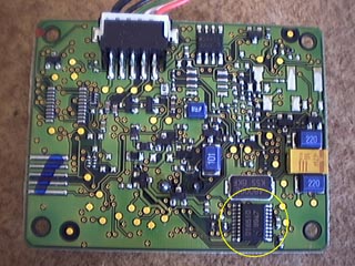 |
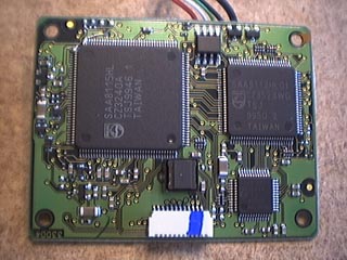
...and this is the bottom of the main board. Notice the 16510 chip, the large black chip, in the lower right corner. This is where the mod must be performed.
|
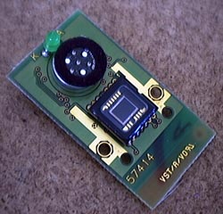 |
This is the front of the CCD board. It shows the green power-LED at the top, the microphone in the middle, and the CCD at the bottom.
|
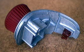 |
This is the lens holder. It screws right off the CCD board, although it takes those strange star-shaped screw-drivers.
|
